Geotechnical & Geological Services(a) Boreholes
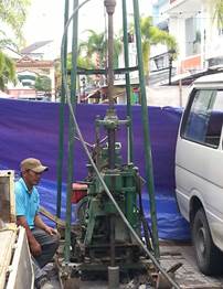
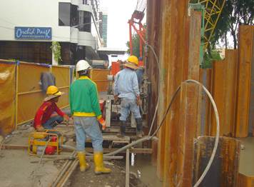
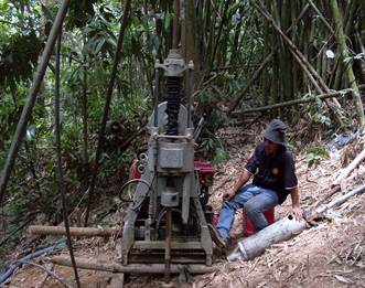
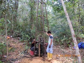
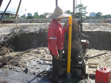
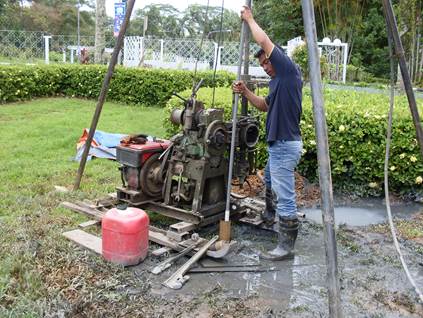
- Rotary Drilled Borehole
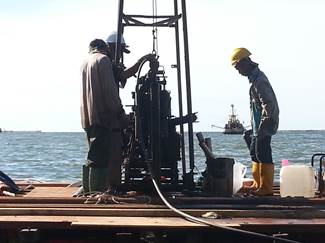
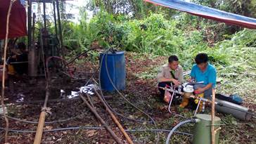
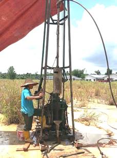
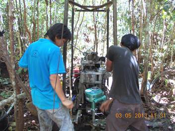
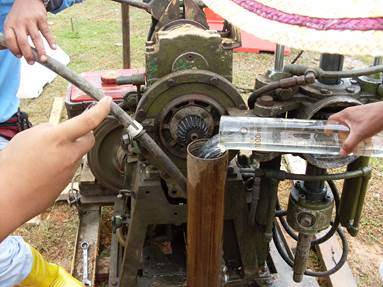
In rotary drilling method, the hole is drilled by a rotating bit to which a downward force is applied. The bit is fastened to, and rotated by a drilling string composed of high quality drill pipe and drill collars with new section or joints being added as drilling progress. The drilling fluid commonly water is pumped down to the bit through hollow drill rods lubricates the bit and flushes the drill debris up the borehole. In the mean time, soil sample are collected using split tube sampler or thin-walled soil sampler for undisturbed samples. The common types of rotary drilling machine are YBM, YWE, TOHO and etc. This drilling technique is very useful in difficult ground conditions or when rock coring is required. Rotary drilling techniques are use in Land such as swampy, normal, slope/hilly area.WATIMA Rotary drilling borehole uses of as followed site:-
1. Land
2. Coastal
(b) Trial Pitting
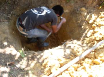
It is an excavation of ground in order to study or sample the composition and structure
of the sub-surface, during a site investigation, a soil survey or a geological survey up to
depth of 3m. This method usually dug by hand using a pick and shovel. Trial pits permit
the in-situ condition of the ground to be examined in detail both laterally and vertically
and allow mass properties to be assessed. Trail pits are particularly useful for investigating
and sampling soils derived from in-situ rock weathering and colluviums, both of which often
exhibit a high degree of variability. Pit may also use to investigate the dimensions and
construction details of old retaining walls, and to ascertain the position of buried utilities
and services.
(c) Packer Or Lugeon Test
Packer or lugeon test gives a measure of the acceptance by insitu rock of water under pressure. The test was originally introduced by lugeon (1933) to provide an acceptable standard for testing permeability of dam foundations. In essence,
it comprises the measurement of the volume of water that can escape from uncased section of borehole in a given time under a given pressure. Flow .is confined between known depth by means of packers, hence the more general name of the test.
The flow is confined between two packers in the double packers test or between the packer and the bottom of the borehole in the single packer test. The test is used to assess the amount of grout that the rock will accept, to check the effectiveness of grouting, to obtain a measure of the amount of
fracturing of the rock (snow, 1968, or to give an approximate value of the permeability of the rock mass adjacent to the borehole. The results of the test are usually expressed in term of Lugeon units. A rock is said to have a permeability of i lugeon if, under a head above ground water level of 100m,
a 1m length of borehole accepts 1 litre of water per minute. Lugeon did not specify the diameter of the borehole, which is usually assumed to be 76mm (N size), but the test is not very sensitive to change in borehole diameter unless the length of borehole under test is small.
(d) In-situ Testing
Disturbed samples are available throughout and a variety of other tests can be performed through the hollow stem, for examples, standard penetration and flied vane shear tests.
Standard Penetration Test (SPT)
The SPT is the most commonly type of in situ test in ground investigation. The tests determine the in situ resistance of soil to the penetration of split barrel sampler. In coarse gravely soil and week rocks, the split-barrel sampler are replaced with solid 60° cone. To begin the test, the sampler is lowered into the borehole and rested at the bottom of the borehole. The penetration under this total dead weight is recorded and if the penetration is more than 450mm the test is omitted.
Geonor Vane Shear Test
The field vane shear test is the most widely used method for measuring the undrained
shear strength and sensitivity of soft clays in-situ. The test is carried out by pushing the vane into undisturbed soil. The vane is then being turned, and maximum torque needed
to shear the soil is recorded.
Permeability Test
Permeability is defined as the ability of water to flow through a saturated soil. In situ permeability tests can be
carried out in soils or rocks, in open boreholes, in piezometers, or in sections of drill hole sealed by inflatable
packers. The three most common types of permeability test are rising and falling head tests, constant head tests and
packer or Lugeon tests.
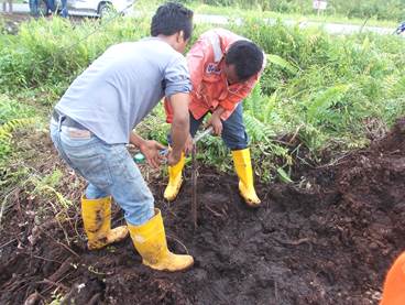
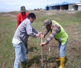
Hand Auger/Peat Auger
This method is a quick and cheap method of boring. It is widely used in remote area where access is difficult or where equipment has to be handled by hand. It causes minimum amount of disturbance to the land can be used to locate soil horizons with high degree of precision. It also can be used for groundwater observation and for installing instrumentation.
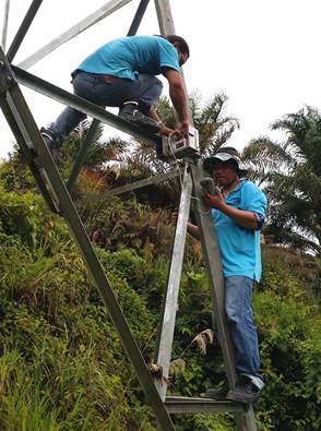
(e) Instrumentation & Monitoring
In order to understand more fully the behavior of particular soils and rocks, instruments can be installed in boreholes.
1) Inclinometer
Inclinometer used to monitor lateral movements in embankment filling, landslide areas, deflections of retaining walls and piles, and deformations of excavation walls, tunnels, and shafts.
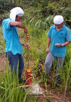
2) Pneumatic Piezometer
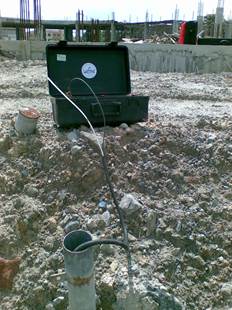
Pneumatic Piezometer is used to measure pore water pressure in saturated soils. Pneumatic
Piezometer comprises 2 air-filled tubes connecting the measuringpoint to a valve located close to the porous element. It is used for monitoring pore pressure to determine safe rates of fill or excavation, monitoring pore water pressure to determine slope stability, to monitoring the effects of dewatering system used for excavation and to monitoring the effects of ground improvement systems.
3) Standpipe Piezometer
Standpipe Piezometer is used to measure pore-water pressure and water level in permeable soils. It consists of a filter jointed to a riser pipe. The readings are obtained with a water level indicator. It used to determine the stability of slopes, embankments, and landfill dikes, ground improvement, dewatering schemes for excavations and underground opening.
4) DGSI Vibrating Wire Piezometer
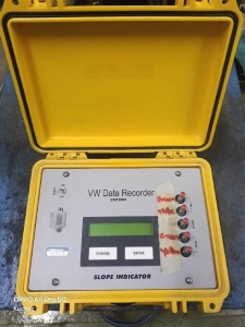
The vibrating wire piezometer converts water pressure to a frequency signal via a diaphragm, a tensioned steel wire, and an electromagnetic coil. The piezometer is designed so that a hange in pressure on the diaphragm causes a change in tension of the wire. When excited by the electromagnetic coil, the wire vibrates at its natural frequency. The vibration of the wire in the proximity of the coil generates a frequency signal that is transmitted to the readout device. The readout device processes the signal, applies calibration factors, and displays a reading in the required engineering unit
5) Digital Portable Tiltmeter
WATIMA using the Digital RST Portable MEMS Tilt Meter utilizes a MEMS tilt meter to measure tilt in two axial planes perpendicular the surface of the base plate. Our MEMS Portable Tiltmeter System with Model ICTS0004 Micro-Electro-Mechanical System (MEMS) Portable Tiltmeter System permits the precise measurement of changes in tilt of engineering structure. The system consists of three component, (1) individual Tiltmeter Monuments which are secured to the structure at points of interest, (2) the MEMS Portable Tiltmeter which indexes the Tiltmeter Monuments in a repeatable manner and senses the tilt via MEMS tilt sensor/s (uniaxial/biaxial), and (3) a MEMS Portable Tiltmeter IC6800S Readout to display the Tiltmeter Data.
The Tilt Monuments are precision-machined stainless steel plates with 4 indexing studs located 90 degrees apart on a 100mm diameter circle. Each stud id numbered from 1 to 4. The Monuments are fastened to the structure of interest by methods which depend on the material of the structure. The stainless steel materials are resistant to corrosion in many construction environments. The MEMS Portable Tiltmeter is a precision stainless steel instrument which can be indexed precisely and in a repeatable manner on the Tiltmeter Monument. It can be fixed in 4 positions which together permit the tilt of the instrument to be sensed along 2 orthogonal axes with normal and reversed readings which permit cancellation of face error. The measurement is made via a MEMS tilt sensor/s, which converts the tilt measurement to a highly precise analog signal. The Tiltmeter is typically read via the RST Model IC6800S MEMS Portable Tiltmeter Readout. All Readout are configured to display the data in engineering units of (sine ᶿ).
f) Settlement Monitoring
1) By Precise Leveling
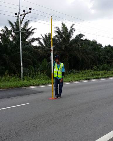
Settlement monitoring is used to monitor the vertical movement of building, ground and embankment surface as well as the surrounding area throughout the construction activities. The permanent reference station or deep leveling datum is used as a reference for leveling measurement to other points, and shall be established on stable ground. The comment types of settlement monitoring are Rod Settlement Gauges, Ground Settlement Marker, Column Settlement Point, On Concrete Surface or On Premix Surface.
2) Settlement Plate/Rod Settlement Gauges
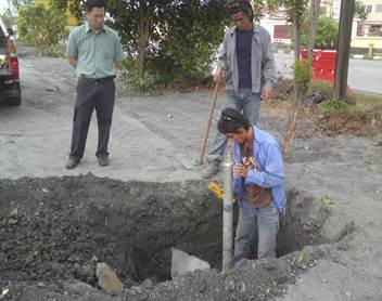
The settlement plate are required to measure the settlements taking place beneath and adjacent to embankments during and after construction period. The settlement plate shall be provided and installed vertically in the position using 25mm diameter G.I. pipe with rounded bottom end. The base plate and first length of rod shall be placed as early as possible during earthworks, preferably before any significant filling has been placed. Continuation gauges shall be installed when the level of compacted embankment is 250mm below the top of the preceding lengths.
3) Ground Settlement Marker (GSM)
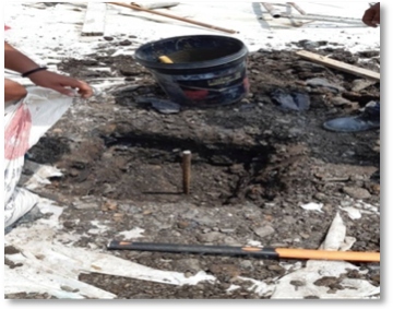
The ground settlement marker with standard steel rods of 20mm diameter and which shall be driven vertically into embankment or undisturbed ground for a minimum depth of 590mm
and shall project approximately 20mm above the ground surface. The rod shall be surrounded by not less than 0.03cu. M of concrete at ground level.
A Ground Settlement Marker (GSM), also known as a Settlement Marker, is a geotechnical monitoring tool used
to measure vertical ground movement-either settlement or heave-over time. Installed on the soil surface or within soft ground,
the markers act as permanent surveying reference points.
4) Building Settlement Marker
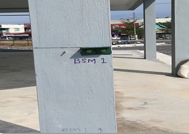
The building settlement marker is used to monitor the vertical settlement / movement of any structure. These reflective markers can be monitored either using total-station or digital level equipment for the most precise readings. It is a simple concrete nail is used to monitor the vertical movement of the structure, especially for the floor slabs of the building structure. The instrumentation works is carried out in order to monitor any settlement for existing structure. Building settlement markers structural can provide early warning of impending structural failures so that analysis and decision can be promptly
|
|||||||||||||||||||||